|
1
|
- Dr Baden Clegg Pty Ltd PO Box
17 Wembley 6913
- Western Australia
www.clegg.com.au
|
|
2
|
|
|
3
|
|
|
4
|
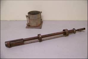
- (which utilizes a drop-hammer with a 5 cm diameter)
|
|
5
|
- Noticing that the pitch
increased with an increase in soil stiffness as the soil is compacted in the mould, Dr
Clegg had the idea in the 1960’s that if the Hammer could be instrumented
to capture this it could be used as a highly portable and rapid means to
assess soil stiffness.
|
|
6
|
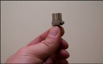
- A product of the space age, developed to measure vibrations of rocket
motors – small, robust and highly accurate.
- By fastening an accelerometer to the 4.5 kg Hammer and analysing the
deceleration versus time curve upon impact with the soil, Dr Clegg and
his researchers at the University of Western Australia’s Department of
Civil Engineering worked out that the peak deceleration could be taken
as a parameter relating directly to soil strength/stiffness, with units
equal to ten gravities providing a convenient scale.
|
|
7
|
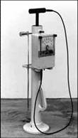
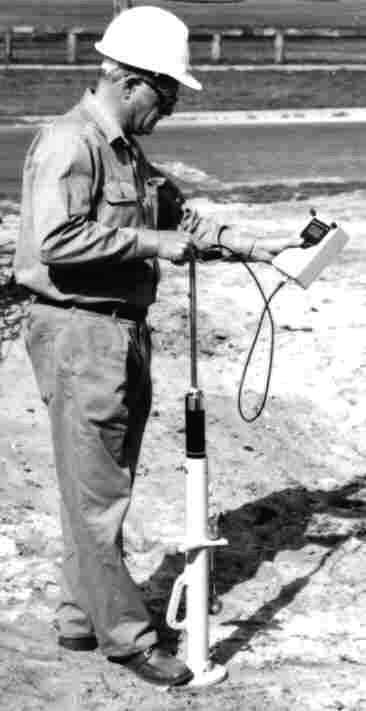
- The University of Western Australia established a company called
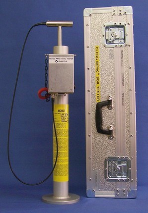
Univention for manufacturing and marketing the device, named by Dr Clegg
the “Impact Soil Tester” but which was called the “Clegg Impact Soil
Tester” or the “Clegg Hammer” by those at the UWA & elsewhere.
- Right photo: Dr Clegg demonstrating the test method
|
|
8
|
|
|
9
|
|
|
10
|
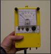
- ◄From This to This►
- An example of improving
- through simplifying
- (made possible by the
- advent of the LCD)
|
|
11
|
|
|
12
|
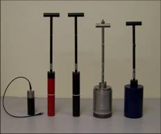
- Left to right: 0.5 kg “Light” Hammer, 2.25 kg “Medium” Clegg Hammer,
- 4.5 kg “Standard” Clegg Hammer, 9.1 kg “Medium Heavy” Clegg Hammer, 20
kg “Heavy” Clegg Hammer
- (There’s also a 10 kg “Heavy
Medium Heavy” Clegg Hammer - special weights can be bolted to the DBC
9.1 kg version to convert it to a 10 kg version, as shown here.)
|
|
13
|
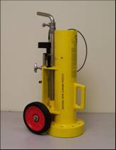
- Clegg Hammers with 13 cm Diameter Drop-Hammers
(Set Drop Height: 0.3 m)
|
|
14
|
|
|
15
|
|
|
16
|
- (1) Dr Clegg’s Revised General Correlation of 1986 for a 4.5 kg Clegg
Impact
- Soil Tester (to ~700 % CBR),
roughly 1/4 of the CIV plus 1, then squaring:-
-
2
- % CBR = [(0.24 × CIV) + 1]
“r” = 0.957
- The equation above was derived from results obtained in Australia, New
Zealand and the UK. These tests cover a wide range of soils for both
laboratory and in-situ testing, unsoaked, non-surcharge conditions.
- (2) Dublin Light Rail Project
Correlation for 2.25 kg Clegg Impact Soil Tester
- for testing in-situ material
prior to construction (to ~50 % CBR):-
- [(Gm (3rd
Drop Result) – 14.936) / 79.523]
- % CBR = e
“R” Squared = 0.9317
- The equation above was derived by engineers working on the Dublin LRT
Project, Civil, Track & Building Works C600, Contractor: MVMBNI JV
in the period October 2001 to January 2003. “Gm” represents “gravity units” peak
deceleration upon impact rather than the “tens of gravities units” scale
of CIV.
|
|
17
|
- Looking first for Vertical Displacement under the centre of the applied
loading (Δ) and then solving for the modulus of elasticity (E),
with certain assumptions:
- Δ = 2 (p )(a) (1 – μ2) / E
- Where p = contact pressure, a = the radius of applied circle of loading,
E = the modulus of elasticity and μ = Poisson’s ratio. Assuming
Poisson’s ratio is 0.5, then:
- Δ = 1.5 (p )(a ) / E
- For a rigid plate (i.e. Clegg Hammer) rather than a flexible plate then:
- Δ = 1.18 (p ) (a ) / E
- Calculating p from force (Clegg Hammer Mass x Acceleration due to
gravity) and the acceleration (deceleration, Gm, i.e. value as measured
by the Clegg Hammer times 10), where the Clegg Hammer radius (in metres)
and drop-height (in metres)
factor into it, and applying an additional factor of 0.6 for
converting square wave used in maths to ½ sin wave type shape as
observed on actual impacts on compacted soils using a CRO and solving
now for E (in Pascals), this becomes:
- E = (1.18) (9.81) (0.6) (Gm ) (Gm) (Hammer Mass ) / π (Hammer
Radius) (Drop-Height)
|
|
18
|
- From the previous slide, the Clegg Hammer Modulus (CHM) for the 4.5 kg
Clegg Hammer (output: CIV) and 20 kg Heavy Clegg Hammer (output: CIV/H)
at their set drop-heights are calculated, in MPa and based on certain
assumptions, as:
- Standard CHM (CHM/S)
- 4.5 kg Clegg Hammer:- CHM/S (in MPa) = 0.088 [(CIV)(CIV)]
- 5 cm Φ Hammer, 0.45 m Drop-Height
- Heavy CHM (CHM/H)
- 20 kg Clegg Hammer:- CHM/H (in MPa) = 0.23 [(CIV/H)(CIV/H)]
- 13 cm Φ Hammer, 0.3 m Drop-Height
- Qualifying remarks:- the coefficients in these equations have been
derived using double integration of time vs. deceleration to determine
the deflection and using this in elastic plate bearing theory to arrive
at an elastic modulus. They depend to some extent on the technique used
for the integration and the theoretical assumptions. The use of Clegg
Hammer Modulus (CHM) as a “seed” modulus for iterative analysis
comparing calculated deflections with field observations should enable
the coefficients to be refined from time to time.
|
|
19
|
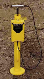
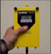
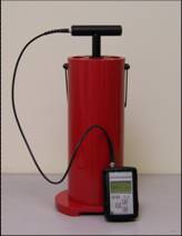
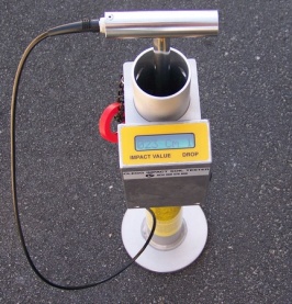
- Wherever, whenever there is evaluation or construction of turf,
earthworks, roadworks or airstrips, the Clegg Impact Soil Tester offers
quick, useful and convenient soil strength/stiffness and uniformity
testing. (GTM-SS-E 4.5 kg or
2.25 kg Model shown – features the meter fastened to the guide tube with
upwards facing display on a timer and a “push and release” button rather
than the “push and hold” button of the Digital Display Model, all which
results in a non hand-held meter.)
- Jim Crandell - Manager
- Postal Address
- PO Box 17, Wembley DC
- Western Australia 6913
- Street Address
- 2/23 Bishop Street, Jolimont
- Western Australia 6014
- Web Address
- www.clegg.com.au
- © Dr Baden Clegg Pty Ltd 2009
|

 Notes
Notes